Plotter, version 2.0
Plotter Version 2: Testing Innovations and Tackling Challenges
In my previous blog post, I shared some initial progress on my plotter project. Since then, I’ve continued improving the machine, leading to a second version with a few updates. Here’s an overview of what I’ve been working on.
Testing the 3D Components
This iteration involved testing some 3D-printed parts designed by Ringo R. Below, you can see how they look in action:
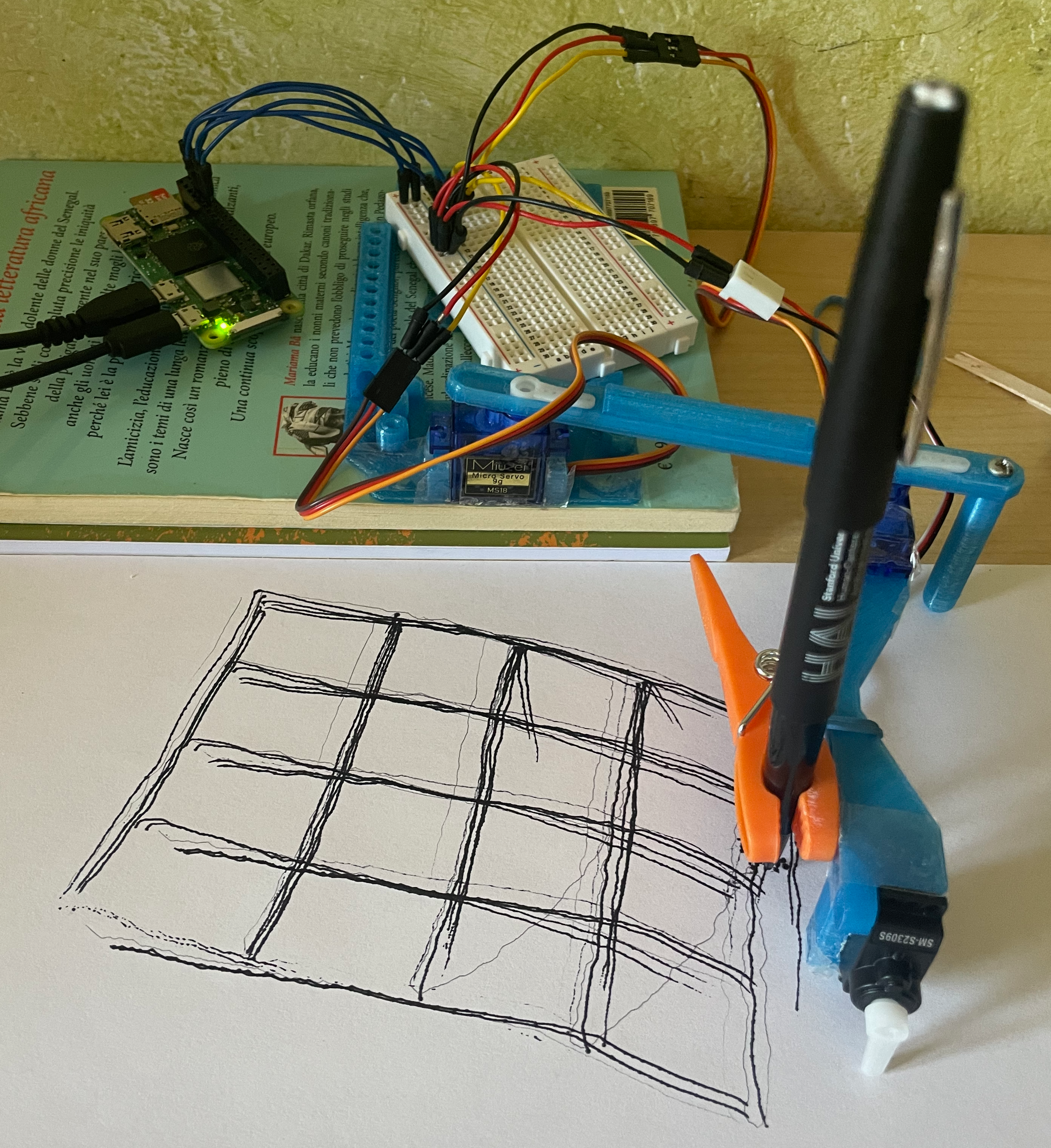
The grid test pattern (bg.test_pattern()) highlights a significant improvement: lines are more consistently parallel and perpendicular. However, as seen in the photo, the 3D components don’t perfectly fit my breadboard or Raspberry Pi. They were originally designed for a larger board with soldered parts. Despite these adjustments, I was quite satisfied with the overall result.
To avoid permanently fixing the servos, I used tape to secure them in place rather than glue. Eventually, I had to glue the servo horns, as they proved challenging to keep firmly attached (even with screws).
Results and Refinements
During testing, I discovered that the image generation tool provided by BrachioGraph software could only convert images to a JSON file (a custom vectorised format used in place of GCODE). The initial outputs were far from ideal: the visualization in Turtle graphics appeared “hairy,” as thicker lines were overfilled with redundant strokes. By tweaking the configuration, I was able to reduce this effect.
To streamline the workflow, I wrote a script that directly converts SVG files to JSON. This allowed me to design patterns in Illustrator or JavaScript and send them straight to the plotter. With this improvement, I achieved accurate single-line traces, as shown below:
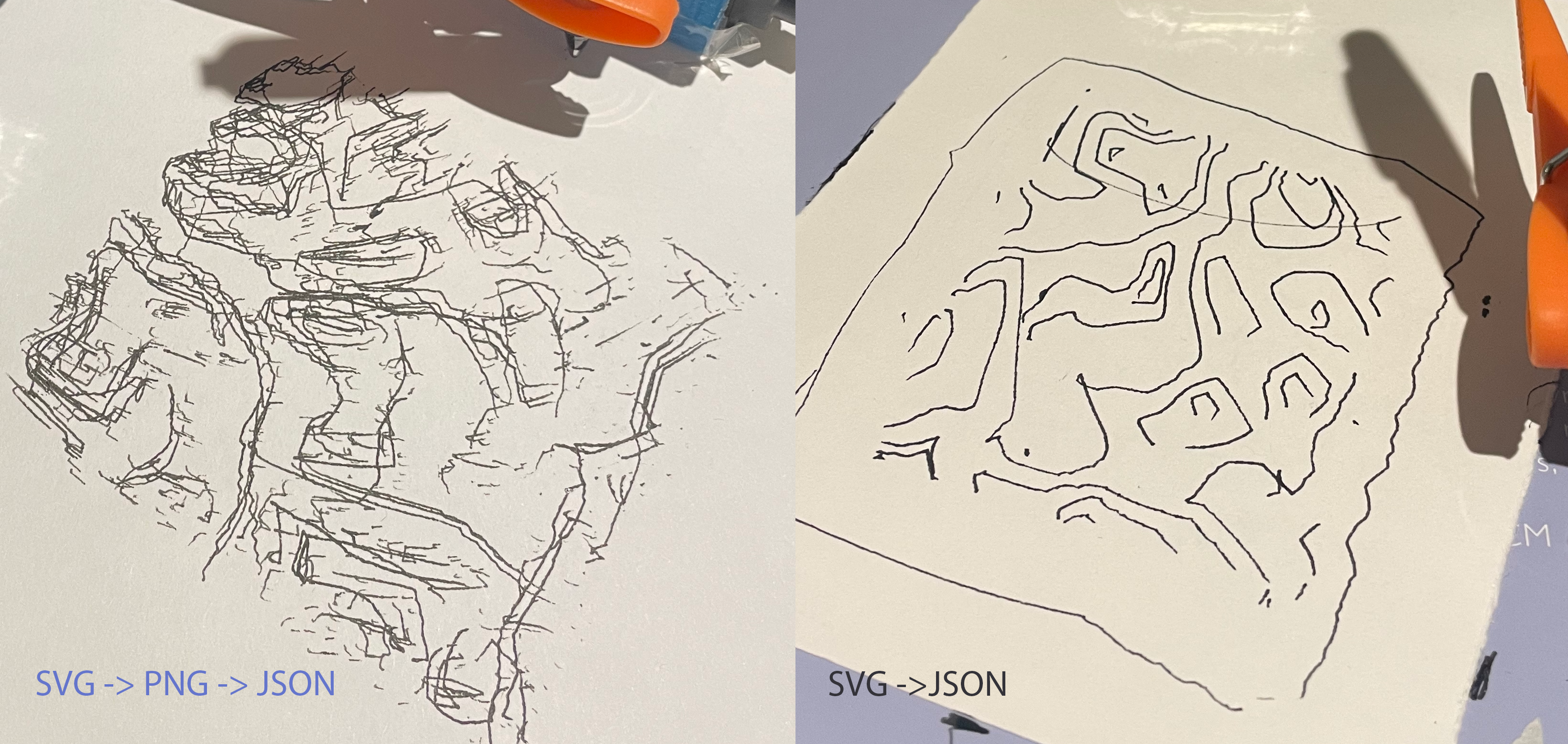
You can find my SVG-to-JSON conversion script here.
Calibration and Challenges
One of the key design considerations was the placement of the shoulder servo, positioned just a few millimeters above the paper. The elbow’s vertical column provides balance for the rest of the arm, but I noticed that using a heavier pen could still flex the outer arm and cause artifacts in the drawings. This happens because the bg.pen.down() command rotates the servo horn, which doesn’t always lower the pen in a perfectly vertical motion.
This realization led me to consider alternative designs, such as an X-Y slider mechanism, which might offer better stability and precision. They might be harder to build though.
Another challenge was ensuring the arm remained steady relative to the paper and table. The servos also created noticeable resistance, affecting positioning accuracy. Interestingly, during a workshop where I used a commercial plotter (Axidraw), I observed similar challenges with placement and calibration, which reassured me that my design had potential.
Calibration has been an iterative and time-consuming process. Each experiment required about 30 minutes of test-pattern drawing before achieving acceptable results. Using the Brachiograph guide, I also attempted to improve output by identifying hysteresis correction coefficients. However, as I progressed, the cheap servos I had used began to fail, making further refinement pointless.
Next Steps
I’ve to confess, it has been a bit demotivating to spend hour after hour on calibration and still not achieve the desired results. I’m considering to design myself different arms that could be more stable and precise. I’m also looking into using a different type of servo, which might offer better performance. Though, I don’t have 3D modeling skills, so I might need to ask for help.
In the meanwhile, I’ve bought a second hand commercial plotter, an A3 Axidraw (first version). I would be able to at least draw some of my sketches while I keep working on my plotter.
Stay tuned for more updates on my plotter project!