<?xml version="1.0" encoding="utf-8"?><feed xmlns="http://www.w3.org/2005/Atom" ><generator uri="https://jekyllrb.com/" version="3.10.0">Jekyll</generator><link href="https://lauraporta.github.io//blog/feed.xml" rel="self" type="application/atom+xml" /><link href="https://lauraporta.github.io//blog/" rel="alternate" type="text/html" /><updated>2025-01-19T21:56:04+00:00</updated><id>https://lauraporta.github.io//blog/feed.xml</id><title type="html">Personal Blog</title><subtitle>A blog about my ideas and thoughts on technology, art and more.
</subtitle><author><name>lauraporta</name></author><entry><title type="html">Plotter, version 2.0</title><link href="https://lauraporta.github.io//blog/2024/12/30/plotterV2.html" rel="alternate" type="text/html" title="Plotter, version 2.0" /><published>2024-12-30T00:00:00+00:00</published><updated>2024-12-30T00:00:00+00:00</updated><id>https://lauraporta.github.io//blog/2024/12/30/plotterV2</id><content type="html" xml:base="https://lauraporta.github.io//blog/2024/12/30/plotterV2.html"><![CDATA[<h2 id="plotter-version-2-testing-innovations-and-tackling-challenges">Plotter Version 2: Testing Innovations and Tackling Challenges</h2>

<p>In my previous blog post, I shared some initial progress on my plotter project. Since then, I’ve continued improving the machine, leading to a second version with a few updates. Here’s an overview of what I’ve been working on.</p>

<h3 id="testing-the-3d-components">Testing the 3D Components</h3>

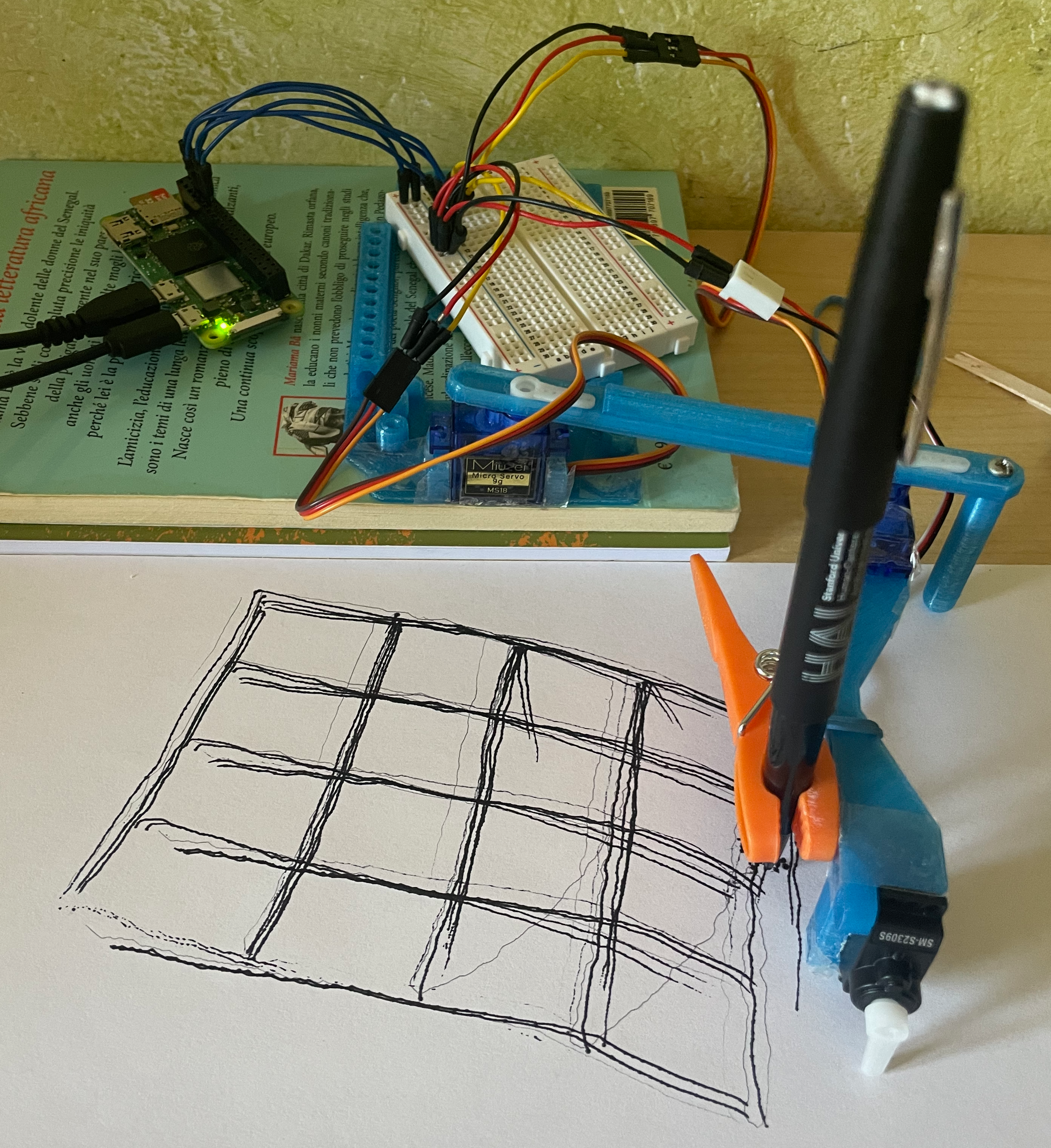
<p>This iteration involved testing some 3D-printed parts designed by <a href="https://www.thingiverse.com/thing:4295302#google_vignette">Ringo R</a>. Below, you can see how they look in action:</p>

<p><img src="https://lauraporta.github.io/blog/images/2024-12-30-plotterV2/IMG_2743.png" alt="IMG_2743" /></p>

<p>The grid test pattern (<code class="language-plaintext highlighter-rouge">bg.test_pattern()</code>) highlights a significant improvement: lines are more consistently parallel and perpendicular. However, as seen in the photo, the 3D components don’t perfectly fit my breadboard or Raspberry Pi. They were originally designed for a larger board with soldered parts. Despite these adjustments, I was quite satisfied with the overall result.</p>

<p>To avoid permanently fixing the servos, I used tape to secure them in place rather than glue. Eventually, I had to glue the servo horns, as they proved challenging to keep firmly attached (even with screws).</p>

<hr />

<h3 id="results-and-refinements">Results and Refinements</h3>

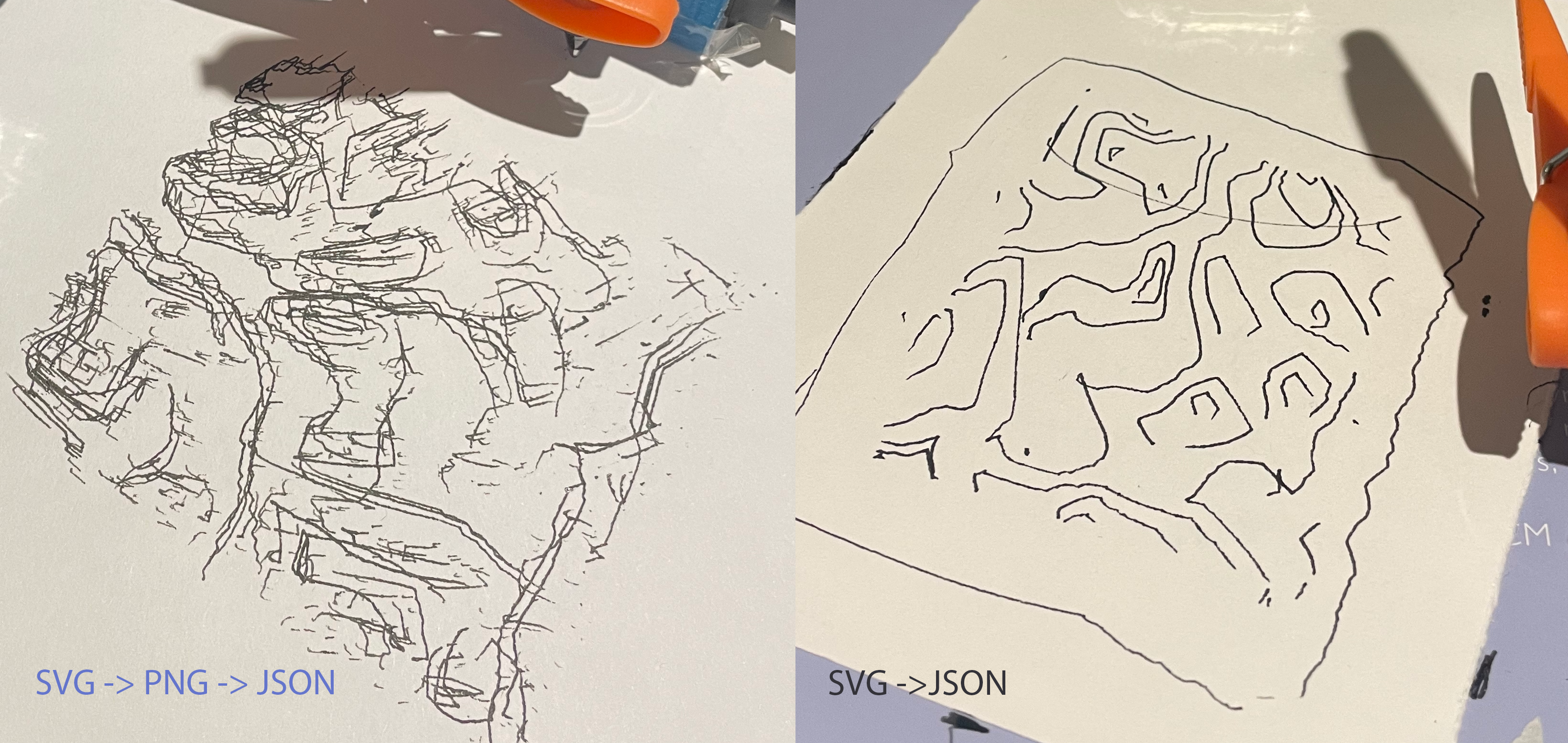
<p>During testing, I discovered that the image generation tool provided by BrachioGraph software could only convert images to a JSON file (a custom vectorised format used in place of GCODE). The initial outputs were far from ideal: the visualization in Turtle graphics appeared “hairy,” as thicker lines were overfilled with redundant strokes. By tweaking the configuration, I was able to reduce this effect.</p>

<p>To streamline the workflow, I wrote a script that directly converts SVG files to JSON. This allowed me to design patterns in Illustrator or JavaScript and send them straight to the plotter. With this improvement, I achieved accurate single-line traces, as shown below:</p>

<p><img src="https://lauraporta.github.io/blog/images/2024-12-30-plotterV2/IMG_3429.png" alt="IMG_3429" /></p>

<p>You can find my SVG-to-JSON conversion script <a href="https://github.com/lauraporta/BrachioGraph/blob/master/svg_to_json.py">here</a>.</p>

<hr />

<h3 id="calibration-and-challenges">Calibration and Challenges</h3>

<p>One of the key design considerations was the placement of the shoulder servo, positioned just a few millimeters above the paper. The elbow’s vertical column provides balance for the rest of the arm, but I noticed that using a heavier pen could still flex the outer arm and cause artifacts in the drawings. This happens because the <code class="language-plaintext highlighter-rouge">bg.pen.down()</code> command rotates the servo horn, which doesn’t always lower the pen in a perfectly vertical motion.</p>

<p>This realization led me to consider alternative designs, such as an X-Y slider mechanism, which might offer better stability and precision. They might be harder to build though.</p>

<p>Another challenge was ensuring the arm remained steady relative to the paper and table. The servos also created noticeable resistance, affecting positioning accuracy. Interestingly, during a workshop where I used a commercial plotter (Axidraw), I observed similar challenges with placement and calibration, which reassured me that my design had potential.</p>

<p>Calibration has been an iterative and time-consuming process. Each experiment required about 30 minutes of test-pattern drawing before achieving acceptable results. Using the Brachiograph guide, I also attempted to improve output by identifying hysteresis correction coefficients. However, as I progressed, the cheap servos I had used began to fail, making further refinement pointless.</p>

<hr />

<h3 id="next-steps">Next Steps</h3>

<p>I’ve to confess, it has been a bit demotivating to spend hour after hour on calibration and still not achieve the desired results. I’m considering to design myself different arms that could be more stable and precise. I’m also looking into using a different type of servo, which might offer better performance. Though, I don’t have 3D modeling skills, so I might need to ask for help.</p>

<p>In the meanwhile, I’ve bought a second hand commercial plotter, an A3 Axidraw (first version). I would be able to at least draw some of my sketches while I keep working on my plotter.</p>

<p>Stay tuned for more updates on my plotter project!</p>]]></content><author><name>lauraporta</name></author><summary type="html"><![CDATA[Plotter Version 2: Testing Innovations and Tackling Challenges]]></summary></entry><entry><title type="html">Plotter, version 1.0</title><link href="https://lauraporta.github.io//blog/2024/08/24/plotterV1.html" rel="alternate" type="text/html" title="Plotter, version 1.0" /><published>2024-08-24T00:00:00+00:00</published><updated>2024-08-24T00:00:00+00:00</updated><id>https://lauraporta.github.io//blog/2024/08/24/plotterV1</id><content type="html" xml:base="https://lauraporta.github.io//blog/2024/08/24/plotterV1.html"><![CDATA[<h1 id="plotter-️">Plotter 🖊️🤖</h1>
<p>I am building my own plotter by following the <a href="https://www.brachiograph.art/">BrachioGraph</a> tutorials. My goal is to create a machine that I can customize to meet my specific painting and drawing needs. BrachioGraph is great because I can minimize the material cost, and the software driving the arms movement is open source and in Python, making it easier for me to add my own twist if I wish. I want to use the drawing machine in my painting or drawing process, but the specifics of it are still unknown to me.</p>

<h2 id="building-version-1">Building version 1</h2>
<p>From BrachioGraph documentation:</p>
<blockquote>
  <p>A BrachioGraph can be built for about €15 in an hour or so</p>
</blockquote>

<p>Well, it definitely took me more than an hour. It was my first time using a Raspberry Pi and before I think I soldered only once. I was (still am) clueless on electronics. I would say it took me a month. I could only dedicate a few hours here and there…</p>

<p>Which materials did I use?</p>
<ul>
  <li>a Raspberry Pi Zero 2 W</li>
  <li>clothes pegs</li>
  <li>a breadboard</li>
  <li>various jumper wires</li>
  <li>very cheap servo motors</li>
  <li>wood sticks from a café</li>
  <li>glue</li>
  <li>pen / pencil / charcoal</li>
</ul>

<p>The overall cost of all materials together remained below 30£.</p>

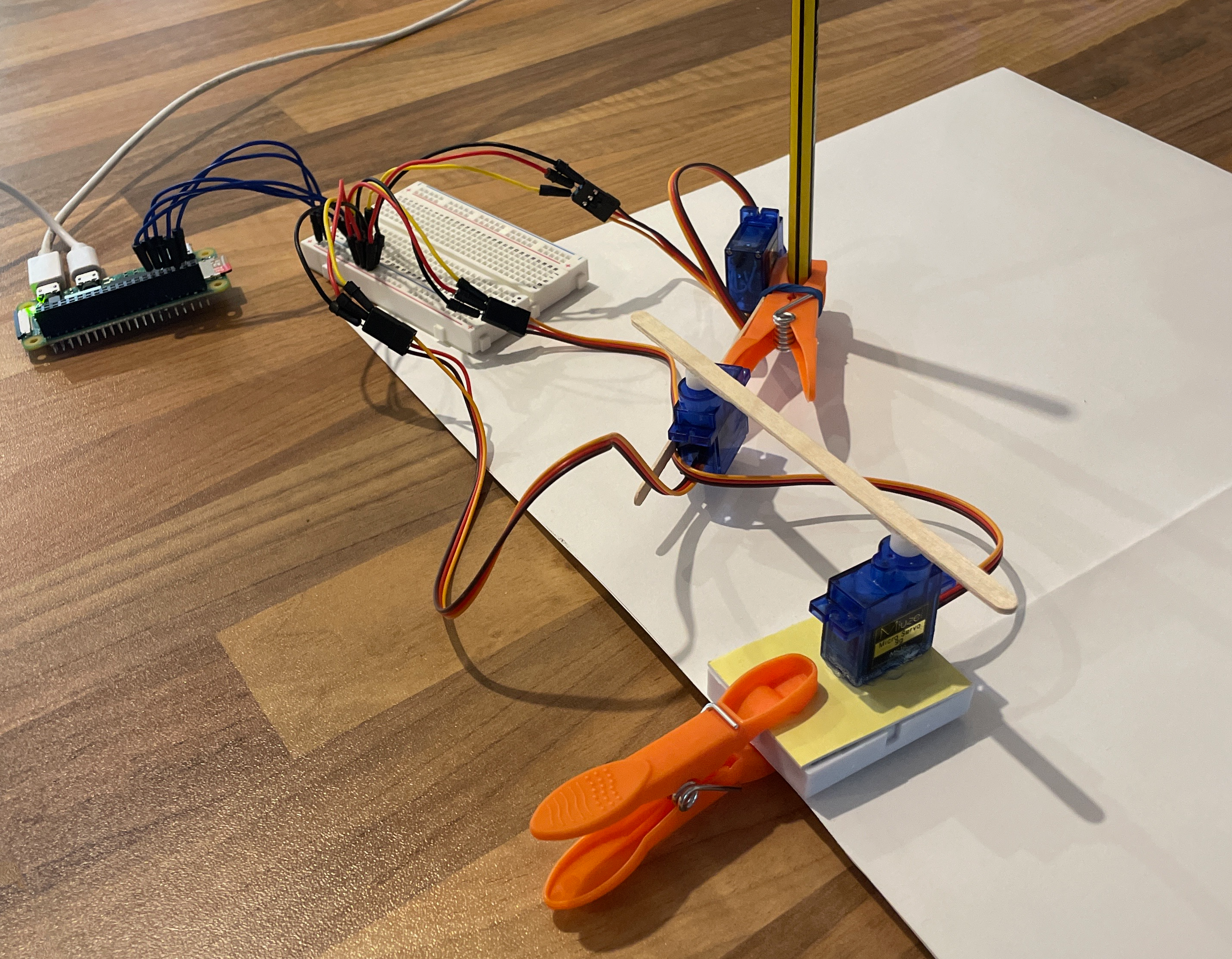
<p>This is the assembled plotter, version 1:</p>

<p><img src="https://lauraporta.github.io/blog/images/2024-08-24-plotterV1/IMG_1378.png" alt="IMG_1378" /></p>

<p>Here you can see how version 1 looked like with a pencil. The “shoulder” servo needed to be lifted up from the paper to have enough gap to lift the pencil up and down. Here I glued it to a spare breadboard, and clipped it to a piece of paper to make it stable. I tried several mediums: pens, pencils, charcoals, chalk. In general, a medium that works well is one that does not require pressure from the top in order to release the pigmented material. A soft pencil (8B) works well.</p>

<p>I then started to plot simple shapes and noticed there were plenty of deformations. They give somehow a playful effect.</p>

<p><img src="https://lauraporta.github.io/blog/images/2024-08-24-plotterV1/IMG_2645.png" alt="IMG_2645" /></p>

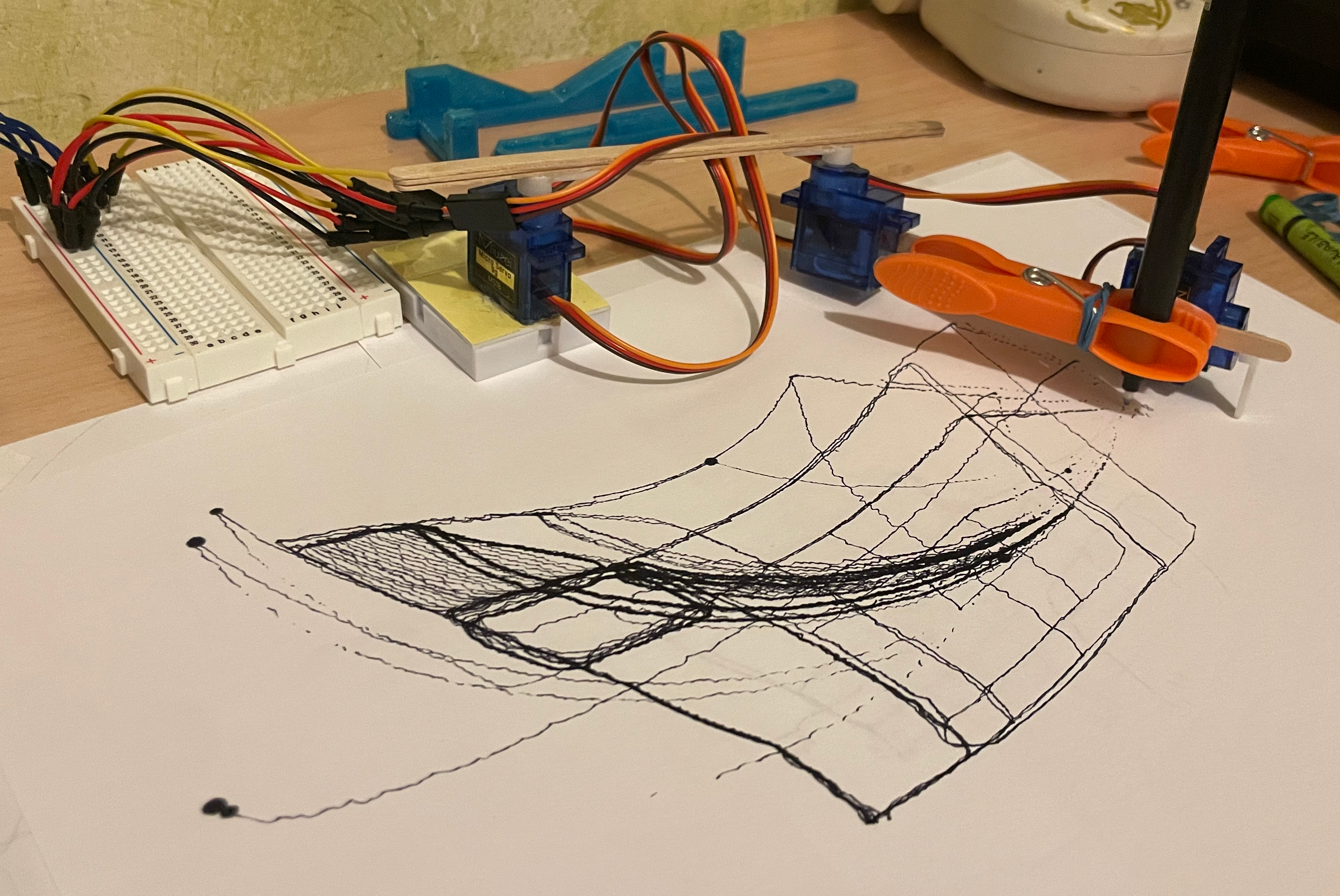
<p>In this photo, you can see that I fixed the support of the shoulder servo to my desk with tape. Paper was fixed to the table with tape as well. I found this setup more stable than the one in the previous photo. I experimented with a pen here aiming to make rectangles. The arcs you see are the trajectories of the pen towards the starting points of the rectangles and shouldn’t have been drawn. They appeared because the wood sticks bent and the pen touched the paper in certain areas. The thick dots are due to the pen resting in one spot for too long.</p>

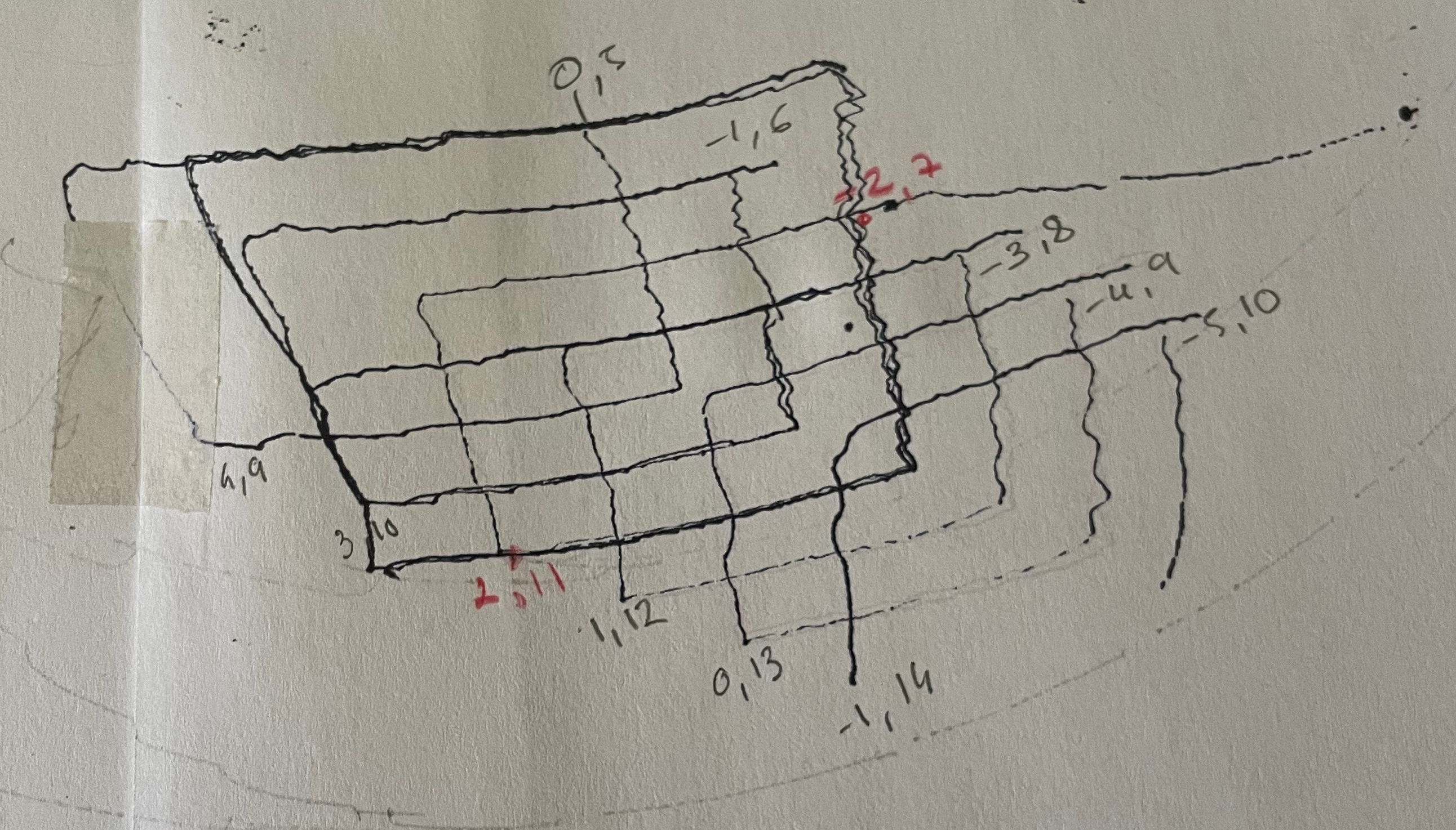
<p>I wanted to make a simple composition just with rectangles. To draw them I used the method <code class="language-plaintext highlighter-rouge">bg.box()</code> and provided the <code class="language-plaintext highlighter-rouge">bound</code> parameter, giving the coordinates of two points. I was struggling to map these coordinates to the space on the paper, but at the end I figured it out (maybe). Here some coordinates sketched on a practice paper.</p>

<p><img src="https://lauraporta.github.io/blog/images/2024-08-24-plotterV1/IMG_2689.png" alt="IMG_2689" /></p>

<p>As you can see from the example, this is a good prototype but has a few points to be improved:</p>
<ol>
  <li>its position relative to the paper is unstable—I need something better than tape;</li>
  <li>the area in which it can draw is limited to a surface about the size of an A5 paper.;</li>
  <li>the wood sticks are soft and bend when the servos rotate, causing deformations.</li>
</ol>

<p>I’ve a few ideas for solving these problems:</p>
<ol>
  <li>I can design a new holder for the shoulder servo. It can be mobile (to be mounted on a canvas); or immobile (connected to a a surface in which to place paper);</li>
  <li>I can design different arm sizes or arms which length can be regulated;</li>
  <li>use a 3D printer to print custom arms.</li>
</ol>

<p>In version 2.0, I’ll rebuild the plotter using 3D-printed arms designed by <a href="https://www.thingiverse.com/thing:4295302#google_vignette">another hobbyist</a> who followed the BrachioGraph tutorial. I’m looking forward to seeing if the rigid arms will eliminate the deformations!</p>]]></content><author><name>lauraporta</name></author><summary type="html"><![CDATA[Plotter 🖊️🤖 I am building my own plotter by following the BrachioGraph tutorials. My goal is to create a machine that I can customize to meet my specific painting and drawing needs. BrachioGraph is great because I can minimize the material cost, and the software driving the arms movement is open source and in Python, making it easier for me to add my own twist if I wish. I want to use the drawing machine in my painting or drawing process, but the specifics of it are still unknown to me.]]></summary></entry></feed>